Installation13 min read
Array layout and row spacing: the shading-density trade-off
A worked-trigonometry guide to inter-row shading geometry, solar altitude at the design hour, and how ground coverage ratio trades off against annual shading loss.
Most solar failures are not electrical. They are mechanical, and they start at the moment someone drills a hole in a roof.
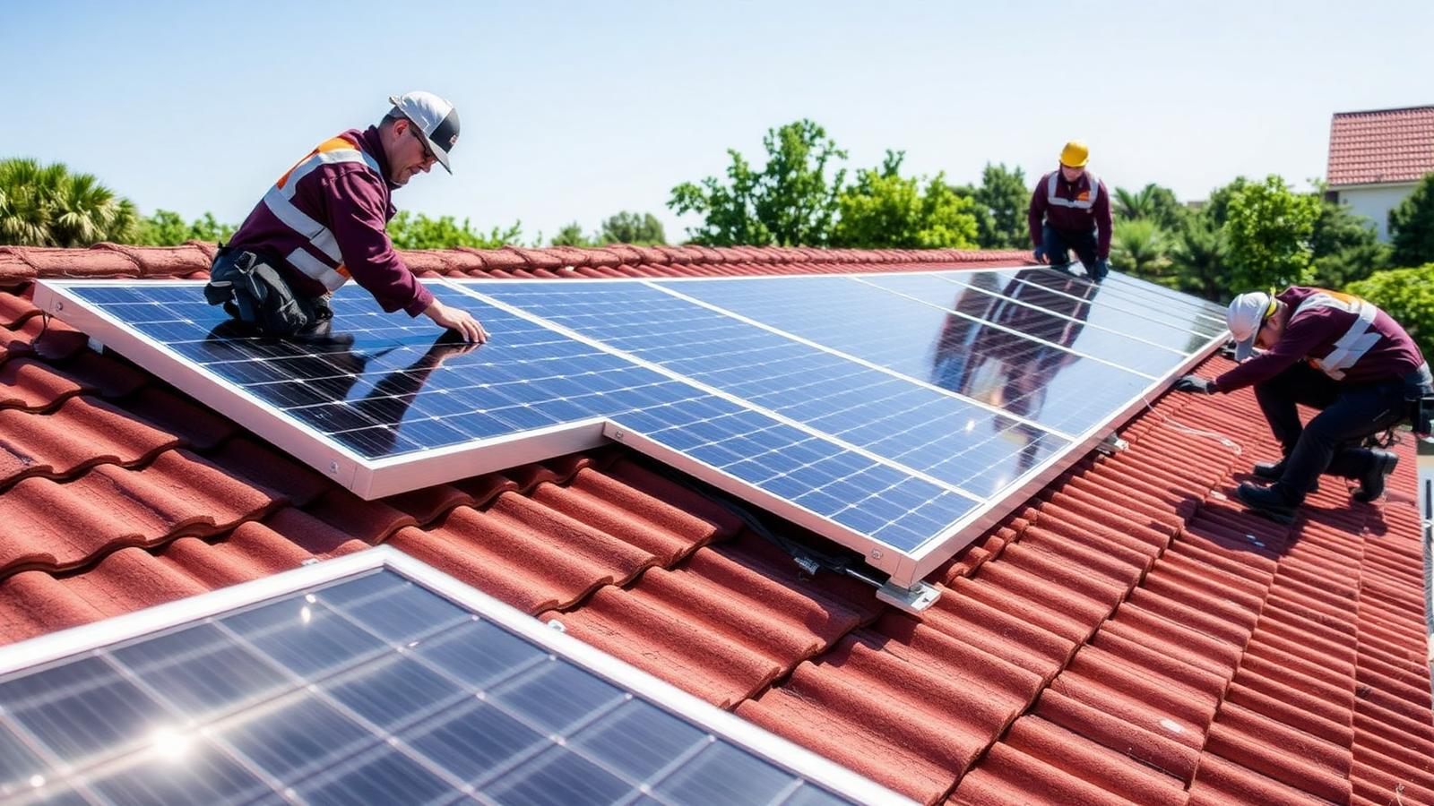
Ask any experienced installer what causes callbacks and the answer is rarely the panels. It is water finding a path it should not have, or a clamp that worked loose, or a rail span that was too long for the wind zone. The array will outlive the roof it sits on only if the interface between them is treated as roofing work rather than as an afterthought to the electrical design.
Before anyone sketches a panel layout, three things need answering: what the roof covering is, what the structure underneath it looks like, and how much life the covering has left.
A twenty-year-old concrete tile roof with another twenty-five years in it is a good host. A bitumen membrane with eight years left is not — you will be paying to remove and refit the array halfway through its life. The honest conversation about re-roofing first is cheaper than the alternative.
Structurally, you need rafter or purlin spacing, member size, and span. A typical pitched domestic roof carries the array easily; the added dead load is around 12 to 18 kg per square metre. The problem is almost never total weight. It is point loading at fixings and uplift.
Wind does not push a panel onto a roof. It pulls it off. Airflow accelerating over the ridge creates suction on the leeward face, and the highest suction coefficients occur at roof edges and corners — often two to three times the value in the field of the roof.
Design codes such as EN 1991-1-4 divide a roof into zones for exactly this reason. Practical consequences:
Snow adds the opposite problem. Snow load acts downward and is amplified where panels create a smooth surface that lets snow slide and pile at the eaves. In alpine regions, snow guards below the array are not optional.
The standard approach is a stainless steel hook fixed through the batten into the rafter, with the tile above it either ground out locally or replaced with a modified tile so it seats flat. Two failures recur: the hook bearing on the tile below it, which cracks the tile after a few thermal cycles, and fixing into the batten alone, which pulls out under uplift.
The hook must clear the tile beneath by a few millimetres, and the fixing must reach solid rafter timber with adequate embedment — typically 60 mm minimum in softwood for a coach screw.
Slate is unforgiving because you cannot grind it. Use a hook designed for slate with a matching lead or aluminium flashing slid under the course above, or a purpose-made replacement slate with an integrated flashing. Never rely on sealant alone between slates; slate roofs work by overlap and gravity, and a bead of silicone is a five-year solution to a twenty-five-year problem.
The best case. Clamps grip the seam mechanically with no penetration at all. Check the clamp is rated for the specific seam profile and that the setscrew torque is what the manufacturer specifies — over-torquing deforms the seam and under-torquing lets it slip.
Two philosophies. Ballasted systems avoid penetrations and rely on weight, which demands a structural check because ballast can add 60 to 100 kg per square metre. Mechanically fixed systems penetrate, and each penetration must be flashed and welded or bonded by someone who knows that membrane system — often the roofing manufacturer will only honour the warranty if their own approved installer does it.
The principle in roofing is that water is managed by overlaps and gravity, and sealants are a secondary defence with a finite life. Every penetration should be flashed so that water running down the roof passes over the flashing and back onto the covering below.
Where a sealant is genuinely required — around a bolt shank, for instance — use a butyl or EPDM sealing washer designed for the purpose, not a general-purpose silicone. Silicone in contact with some membranes and with certain metals will fail or corrode.
Aluminium expands about 0.023 mm per metre per degree Celsius. A 10 metre rail run experiencing an 60 °C swing between winter night and summer afternoon moves close to 14 mm. If both ends are fixed rigidly, that movement goes into the fixings, and eventually one of them loses.
Use the manufacturer's expansion joints at the specified interval, or split long runs. Leave the gap they specify between rail sections — it is not a tolerance, it is a design feature.
Module clamps have a torque specification and a permitted clamping zone marked in the module installation manual. Clamping outside that zone voids the module warranty and, more importantly, concentrates stress in the frame corner where glass breakage starts. Mid-clamps must engage both adjacent module frames evenly.
DC cables left resting on a tile or looping below the array will chafe through their insulation within a few years of wind movement, and a DC arc fault on a roof is the one failure mode with genuine fire potential.
Practical rules:
A meter reading of "it works" catches nothing. The checks worth doing:
Insulation resistance between each pole and earth with the array isolated. Values below the inverter's threshold mean water ingress somewhere, and finding it in dry weather is far easier than in December.
Open-circuit voltage per string, compared against the calculated value for the measured cell temperature. A string reading low by roughly one module's worth of voltage means a module or a diode is not contributing.
Short-circuit or operating current per string, compared string to string. A consistent 10 percent deficit on one string points to shading or soiling; an erratic one points to a connection.
Thermal imaging of the array under load. Hot cells, hot connectors and hot junction boxes all show up in a two-minute sweep and take a day to fix now instead of a roof visit in year three.
Torque audit on a sample of clamps and roof fixings, recorded.
Will mounting panels void my roof warranty? It can. Membrane manufacturers in particular often require an approved contractor to make and certify penetrations. Check before the array is designed, not after.
How far should panels be set back from the roof edge? Enough to stay out of the high-suction corner zones and to allow safe access — typically 300 to 500 mm, though fire service access requirements in some jurisdictions demand more. Local rules govern.
Do panels damage tiles? Correctly installed hooks do not. Tiles crack when a hook bears on the tile below, when installers walk on unsupported tile centres, or when a ground-out tile is left with too little material at the tail.
Is a ballasted flat roof system safe in high wind? Only if the ballast calculation used the correct wind zone, terrain category and building height, and only if a structural engineer confirmed the roof can carry it. Ballast is a real engineering calculation, not a rule of thumb.
Photograph every penetration before the tile goes back. Twenty photographs at the start of an install cost ten minutes and settle every future argument about whether a leak came from the array or from the flashing around the chimney. Good installers document; careless ones remember.
Standards are cited for orientation. Always work from the current published edition and the national annex that applies in your jurisdiction.
First published.
Technical review: worked examples re-derived, standards references checked against current editions, sources verified.
A worked-trigonometry guide to inter-row shading geometry, solar altitude at the design hour, and how ground coverage ratio trades off against annual shading loss.
A technical comparison of ground-mount and roof-mount PV covering yield, tilt freedom, foundations, cost per kWp, cabling, permitting, and O&M access.
How EN 1991-1-3 and 1991-1-4 govern PV mounting design, from terrain factors and edge zones to uplift arithmetic and roof capacity checks.